
تبلیغات
موضوعات
جستجو
پیوندهای روزانه
لینک دوستان
- دریافت رایگان این قالب
- سایت عاشقانه ماندگار فان
- سایت عاشقانه عشق آفرین
- جامعه رادیو اماتوری ایران
- سازمان تنظيم مقررات و ارتباطات راديوئي
- شرکت اروم الکترونیک
- فروشگاه قطعات الكترونيكي
- ARRL • Devoted Entirely to Amateur Radio
- درددل های یک بازنشسته
- نخستین سایت آموزشی رادیو آماتوری در ایران
- نشریات آماتوری
- EP2MRD
- QRZCQ - The database for radio hams
- شناسه تخصيص نحوه دستورالعمل ايستگاه به ارتباط راديويي هاي ) Call Sign ( دستورالعمل ارتباط شناسه تخصيص نحوه ايستگاه به راديويي
- رادیو آماتوری
- کلوپ رادیو آماتوری ایرانیان
- ارسال لینک
صفحات جانبی
امکانات جانبی
 آمار
وب سایت:
آمار
وب سایت:
بازدید دیروز : 5152
بازدید هفته : 6300
بازدید ماه : 15646
بازدید کل : 1472791
تعداد مطالب : 673
تعداد نظرات : 119
تعداد آنلاین : 1
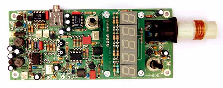
Grade Deep Meter
The heart of the circuit is the varicap tuned variable oscillator with a tuning range of about one octave. The Tuning-Voltage is overlaid by a small sawtooth voltage which causes a symmetrical frequency modulation (sweeping) of the VFO. The chosen frequency sweep is approximately +/- 0.2% of the current oscillator frequency. The sweep frequency is approximately 400 Hz. If DipIt is coupled to a device, DipIt´s frequency will sweep over the resonance curve of the Device Under Test (DUT). This is the same what a user normally does with a conventional Dipmeter by sweeping the Main Tune Knob for a little amount to find the Dip.
Sweeping the VFO by 400 Hz over the resonant curve of the DUT results in an Amplitude Modulation (AM) of the VFO. Why? The DUT will absorb energy of the VFO if it is on the same frequency as the Dipmeter. Because the Dipmeters frequency is swept by 400 Hz, the Amplitude of the VFO will go up and down by 400 Hz - this is what we all know as Amplitude-Modulation (AM). The degree of modulation is greater the more exact DUT and Dipmeter are tuned to the same frequency and the harder the coupling between both is. A following AM demodulation stage separates the 400 Hz AC tone. The display part of DipIt is a simple 40dB AF Amplifier, a rectifier and a superbright LED. Using this method, the only criteria of detecting resonant devices is the AM-Modulation so the different Amplitude height of the VFO depending on its frequency is no longer a problem. That fact, that an AM signal can be amplified very easy increases the sensitivity of the dipper dramatically.
- Coupling between DipIt and DUT can be much looser then with any conventional dipmeter, the dip is absolutely clearly.
- DipIt works as a Direct Conversion Mode Frequency Meter. To make DipIt more flexible, we added a Direct Conversion Frequency Meter.
- With a simple probe made from a piece of coax cable and a capacitor we can connect DipIt via its built in Cinch connector to any RF signal source.
- With its Attenuator, Mixer and separate AF Amplifier DipIt becomes a complete Direct Conversion Receiver working over the same range as it does in Dipper mode. This makes DipIt ideal to measure the output of TX-Mixers, output of bandpassfilters in a TX chain and others. Both DipIt modes together plus the standard Absorption Mode make DipIt a tiny and cheap replacement for a (much more comfortable) Spectrum Analyser.

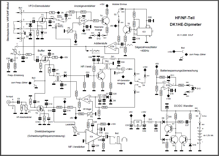
The Circuit:
The VFO is a Hartley Oscillator with a JFET T1 (BF2456B). It consists of the plug in coil L1 and the two anti serial Diodes D1/D2. A 10 turn Pot enables a smooth tuning range of 1 octave. By using 5 different plug in coils, DipIt has a complete range from about 1 to 42 MHz. Because in our opinion its not a good idea to use the same oscillator design for a range from 1 MHZ up to the VHF area, we decided to develop separate plug in Oscillators later for UHF and VHF use. Diode D3 automatically generates the negative Gate Voltage and acts as an AM demodulator the same time. The R/C circuit R2/C2 is a lowpass Filter with an upper border of about 4 kHz. At C2 the demodulated 400 Hz signal is taken and connected via S1 to the following Amplifier.
The Sweep Generator
IC3 acts as an R/C oscillator and produces a symmetrically sawtooth of about 400Hz. The Voltage divider R19/R20 reduce the Amplitude of the sawtooth to the value we need. IC2a is working as an adder that adds the sawtooth to the DC-Voltage from R18. At the output of IC2a we find 8V DC plus symmetrically overlaid sawtooth of some 60-80mV. R45 defines the Tuning range. The R/C combination plus Pot P5 form a Voltage divider for the sawtooth part and they linearize the typically S-shaped curve of D1-D2. So the sweep range is nearly constant over the whole VFO range.
Display Amplifier
The 400Hz AC Signal is amplified in IC1a, amplification ratio is 40dB. C15 decouples the AC signal from it’s DC part. By P2 the quiescent level can be adjusted so that the LED outside of a resonant situation is just glowing a little bit. At this point the LED additional acts as a rectifier. If there is an AC signal, the positive half-waves let a current flow through the LED. The brightness is direct proportional to the amplitude of the signal. Transistor T4 serves as current source for the LED, R15 limits the If a user likes to use a needle instrument (Voltmeter) this one can be added parallel to the LED.
Buffer, Power Amplifier and ALC
By C3 the VFO Signal is coupled to a FET Buffer T2. The frequency counter is low impedance coupled at the source of the buffer by BU3. The buffered VFO Signal also is used as Local Oscillator Signal (LO) for the integrated Direct Conversion Frequency Meter. By transformer TR1 the buffered signal is coupled to the power amplifier T6. Amplification is adjusted by R28 to 20dB. Transformer TR2 transforms the dynamic collector resistance of T6 to the system impedance of 50 Ohm. This amplified RF Signal can be taken from DipIt at the Signal Generator Output Jack BU 6. To get a constant level of +7dBm independent from the actual frequency, the circuit around T6 is designed as VCA, Voltage controlled Amplifier. The actual output is decoupled by R29 and rectified by D6/D7. The resulting Voltage is feed as an “IS” Voltage to the inverting input of IC1b. The Output is controlled by the “To BE” Voltage at the non inverting input of IC1b. PIN Diode D5 together with R23 act as a RF Voltage divider. So if the Actual rectified RF Voltage is lower at PIN 6 of IC1b is lower then the control Voltage at PIN 5 IC1b, the output of IC1B gets positive causing a higher current in D5 which makes it’s dynamic resistance lower. The RF Input at the Base of T6 increases until the rectified RF output Voltage has the same value as the control voltage.
Direct conversion Frequency Meter
We integrated an instrument into DipIt which was an absolutely “MUST HAVE” for long times but has been nearly forgotten the last years: the Direct Conversion Frequency Meter or Zero beat Frequency Meter because it extreme useful to have it when building Amateur Radio Kits without access to other frequency selective metering devices like Spectrum Analysers. We use a MOS Tetrode as Direct Conversion Mixer. Gate 1 is coupled to the input Jack Bu5 by a variable attenuator P1, Gate 2 gets the LO signal from the Buffer Circuit. The output of the mixer T3 is coupled to the Display by switch S1 and amplified by IC4 to control it by headphones. If DUT frequency and VFO frequency are nearly the same, the conversion tone will be heard in the headphones. If the VFO is tuned to “ZEROBEAT” , that is the frequency where the tone just disappears, the frequency-counter will show the exact frequency of the measured DUT signal. The Sweeper must be shut off during this measurement!
Absorption Frequency Meter
If Switch S1 is switched to Absorption, the input of the Display Amplifier is coupled to the direct conversion Mixer. Now additional to the acoustic control DipIt offers an optical control which gives us some quantitative meaning. This can be used to find a maximum of an Bandfilter per example. The strength of the RF at BU5 will be displayed by the LED, its brightness is direct proportional to the strength of the signal. BU5 can be coupled to a DUT by a coaxial cable and a small Cap. Attenuator P1 shout be adjusted to hold the brightness of the LED much below its maximum to make it possible to see small differences in signal level. This Method is a very sensitive variant of the classical Absorbtion measurement. It is extreme useful while optimising / maximizing TX stages. If the frequency of the DUT is not stable, the sweeper can be switched on. In this case the frequency modulated VFO detects the DUT signal which now can be detected and adjusted if the drift is not more then about 8kHz.
Voltage Control
Because a Dipmeter is used periodically, we decided to use Alkaline AA cells instead of accumulators because due to the self-unloading of NiMH cells we assume that DipIt has no power every time you will use it. The 4 Alkaline AA cells give us a Voltage of 6V. Because we need an internal Voltage of 10 Volt, DipIt uses a Voltage converter. T7, T9 and DR8 form the Current Converter, C37/R38 determine the switch frequency. The converter output voltage loads the capacitor C35 via a Schottky–Diod D8. Zener Diode D8 and Transistor T8 clamp the output to 10 Volt. The minimum Input Voltage for the converter is about 4 Volt which gives a ood utilization of the batteries.
Batteries control
To control the status of the batteries, an optical control has been integrated into DipIt. Comparator IC2b compares the divided Voltage (R40/R41) of the regulated 8V output with the voltage of the batteries. IfBattery voltage drops below 4,4 Volt, the control LED goes to ON state which indicates that the Batteries are next to die.
Frequency read out
DipIt uses a well known counter which was designed by our friend DL4YHF. Resolution below 10 MHz is 100Hz and above 10 MHz 1kHz which is much better then any other Dipmeter can do. The counter has been designed as a plug in module to make it available for other QRP projects. Because it has an easy programmable additive / subtractive part it can be used for small transceivers with Superhet RX as well.
It’s A kit
As all other Designs of the German QRP Club, a kit is available from QRPproject. http://www.qrpproject.de/ QRPproject started shipment of kits on May 15. 2006. Because the extreme high number of orders, from the very beginning the waiting time is about 4-5 weeks. We hope to decrease waiting times soon.
Download the complete Dipper-Schematic here.
Download the englis manual here
Manual addon: Wirinig of the switches:
The DipIt-Kit comes complete with double sided industrial PCB, all parts, an Industrie made Alu Enclosure, all cuts and drills already done. The Counter is included. English manual.
http://www.qrpproject.de/UK/dipit.htm
ورود کاربران
عضويت سريع
پشتيباني آنلاين
آمار
خبرنامه
آخرین نطرات کاربران
 AEC - درود
استاد ممنون خیلی خوب و عالی
 پرویز مهرزاد - سلام درود جناب عبداحق عزیز بسیار خوشحالم که وب سایت شما با مطالب مفید وعالی فعال شده است.
پاسخ:باسلام و تشکر از لطف و مرحمت شما دوست عزیز و گرامی - 1400/8/28
پرویز مهرزاد - سلام ودرود استاد عبدالحق عزیز بسیار خوشحالم که سایت جنابعالی بامطالب جدید وعالی دوباره فعلیتش را شروع نموده است.پاسخ:با سلام تذکر بجا و بموقعی بود بسیار متشکرم - 1400/8/28
ایزدی - یه مشکلی داره این طرح. کل سلف ها با هم 12. 7 میکرو میشه که با خازن 270 پیکو، فرکانس مرکزی فیلتر 2.7 مگا هرتز می شه. کمترین سلف هم (0.1 میکرو) با همون خازن 270 پیکو 30 مگاهرتز رو رد می کنه. بنا بر این نیازی به خازن های دیگه نیست. دوستان دیگه نظرشون چیه.پاسخ:باسلام و تشکر کل خازن ها و سلفها برای فرکانس 1800کیلو که ابتدای باند رادیو اماتوری است کم است و بسختی تنظیم می شود اما برای 3500 بله زیاد است - 1399/8/24
هومن - سلام .علت استقبال نکردن در خور توجه همین نا واردیست .این مطلب بسیار گنگ و پر از اشتباه هست پاسخ: سلام بنده هم ضمن تائید نظر شما درخواست می کنم مطلب کامل تر و بهتر و درست تر را بفرمائید بنده بنام خودتان درج و منتشر نمایم
پاسخ:https://t.me/joinchat/AAAAAEJj30AwLGIyi_UQ3g مدارات لامپی - 1396/12/17
علی - سلام شما مکتبی و انقلابی هستید درسته ؟پاسخ: سلام بهیچ عنوان و تقریبا هیچ جائی من چنین ادعائی نکرده ام اما این همه شهید و زخمی و جانباز و اسیر و زحمت و فعالیت برای حفظ انقلاب و سرزمین عزیزمان ایران خیلی حرام لقه گی و بی اصل و نصبی می خواهد که چشم خودرا ببندیم و از این اب و خاک حمایت و به این مردم عشق نورزیم حالا شما اسم انرا هرچه دوست دارید بگذارید نظرتان محترم است - 1396/12/17
هومن - سلام بنده یکی از علاقمندان لامپ هستم . و 10 سال اخیر را بر روی مدارات لامپی کار کردم .با سرچ اینجا را پیدا کردم .می خواستم ببینم در زمینه مخابرات فعالیت لامپی در ایران هست ؟
این مطلب راجب لامپ واقعا توجه مخاطب علاقمند را جلب می کند ؟
من فکر می کنم نویسنده اصلا راجب لامپ حس خوبی ندارد .عذر خواهی می کنم
پاسخ:سلام دوست عزیز از صراحت و فصاحت بیان شما خوشحالم مطلبتان راجع به نویسنده مطلب لامپ کمی کم لطفی و شاید سخت گیری در بر دارد نویسنده مطلب استاد عاملی بزرگ رادیو اماتوری ایران هستند و مطلب را بی اندازه ساده و اسان گفتند چون اکثر جوانها از لامپ و ولتاژ کار ان وحشت داشته و تقریبا هیچ نمی دانند اما ظاهرا شما در مورد لامپ مطلع و ازموده هستید لذا برخود نگیرید شما هم اگر در مورد لامپ و یا مطالب استاد عاملی نقد و نظری دارید بسیار خوشحال می شوم مکتوب بفرمایید تا در همان بخش یا در بخش جدید بنام خودتان منتشر شود
پاسخ:https://t.me/joinchat/AAAAAEJj30AwLGIyi_UQ3g - 1396/12/16
سعیدی - سلام استاد بنده بی جواب ماندم پاسخ:با سلام و پوزش از تاخیر طبق تجربه دوستان این مدار به دلیل نامرغوب بودن قطعات نو موجود در بازار معمولا در ابتدا کار نمی کند لذا بتوصیه استاد عاملی بهنر است از قطعات اوراقی رادیو و ضبط ها استفاده شود قطعات معمولا در گیر این رادیو ابتدا ای سی سویچ یا کلید زنی است که یک مدل خاصش برای مدار مناسب است و مدلهای دیگر فرکانس کار و ولتاژشان مناسب نیست درمورد ای سی مدولاتور و دمدولاتور 3028 این ای سی هم بشدت مورد شک و شبهه است در موردی باتعویض 5 عدد ای سی دو عدد که بهتر بود در مدار بکار گرفته شد لذا بهترین روش استفاده از مرحله مرحله و گام بگام کار کردن رادیو است ضمن انکه اگر فرستنده کار بیفتد گیرنده هم کار خواهد کرد و بالعکس لذا شما می توانید مدار را از میکروفون در حالت فرستنده یا بلندگو در حالت گیرنده شروع نمایید و اگر مسیر سیگنال جدا باشد در نقشه شما می توانید از تقویت صدا شروع کرده و به دمدولاتور رفته و سپس به فیلتر و بعد میکسر وی اف او و در اخر به فیلتر تنظیم باند بروید و حد اکثر سیگنال و حساسیت را بدست اورید پس فیلتر های رادیویی یا بقول شما توکو ها قسمت اخر تنظیم و تعقیب مدارتان است اگر شد برای اطلاع شما و سایر دوستان مدار را در حالت گیرنده و فرستنده جدا اراعه خواهم داد یا با رنگ مسیر سیگنال را جدا می کنم که راحت تر باشد اگر شما عضو تلگرام هستید در یکی از گروه های رادیو اماتوری بیایید و مستقیما با دوستان سازنده و استفاده کننده رادیو تماس گرفته راهنمایی شوید اگر نه ادرس ایمیلتان را بدهید تا راهنمای مونتاژ را برایتان بفرستم
پاسخ:http://py2ohh.w2c.com.br/trx/ararinhamontagem/montandoararinha.htm
راحل مونتاژ و تست مدار است - 1396/11/5
سعیدی - با سلام خدمت استاد بزرگوارم استاد بنده برزیلی رو ساختم ولی نتونستم موفق بشم صدایی دریافت نکردم توکو هارو هم که میچرخونم انگار بی اثر هست .امکان داره این سه تا آیسی مورد داشته باشن؟ از ایران میکرو خریدم
ممنون میشم راهنمایی بکنید
پاسخ: سلام خیلی از دوستان برای ای سی ها سوکت گذاشتند چون معمولا بار اول مدار کار نمی کند و این ای سی ها بدلایل مختلف مشکل دارند
پاسخ: ضمنا شما کدام شهر هستید و اگر علاقمندید با گروههای تلگرامی کار کنید یا ایمیلتونو بفرمایید کمی توضیحات بفرستم - 1396/9/10
سعید - با سلام استاد تو مدار برزیلی یه رله داریم این کارش چیه ؟ مثلا اگر رله فعال بشه چی میشه؟ یه کلید جا گذاری شده براش .
تو قسمت ورودی موج vfo به 7358 یه cwkeyزده به پایه 3 همین آیسی برای چیه؟
ce keyسرچ کردم کلید مورس آمد میشه توضیح بفرمایید ممنون میشم .
پاسخ:با سلام هنگام فشردن کلید PTT روی میکروفون پایه دوم سیم پیچ رله موجود در مدار زمین شده و سر دیگر این رله به مثبت باطری وصل است باعث عملکرد رله شده و لذا دوکنتاکت ان عمل کرده یکی ورودی گیرنده را بزمین وصل می کند تا امواج فرستنده وارد گیرنده نشده و اسیب نرسانند کنتاکت دیگر رله هم ولتاژ مثبت تغذیه را که در حالت معمولی به خط مثبت گیرنده وصل است قطع و خط مثبت فرستنده را فعال می کند +tx cw key بله کلید مورس است که برای کاردر حالت مورس مولد موج جدا داشته که بجای میکروفون کار کرده و سیگنال را ارسال می کند - 1396/4/26
آرشیو
- مهر 1402
- ارديبهشت 1401
- دی 1400
- آبان 1400
- ارديبهشت 1399
- اسفند 1397
- آذر 1397
- آبان 1397
- خرداد 1397
- ارديبهشت 1397
- فروردين 1397
- اسفند 1396
- بهمن 1396
- دی 1396
- آذر 1396
- آبان 1396
- شهريور 1396
- مرداد 1396
- تير 1396
- خرداد 1396
- ارديبهشت 1396
- فروردين 1396
- اسفند 1395
- بهمن 1395
- دی 1395
- آذر 1395
- آبان 1395
- مهر 1395
- شهريور 1395
- مرداد 1395
- تير 1395
- خرداد 1395
- ارديبهشت 1395
- فروردين 1395
- اسفند 1394
- بهمن 1394
- دی 1394
- آذر 1394
- آبان 1394
- مهر 1394
- شهريور 1394
- مرداد 1394
- تير 1394
- خرداد 1394
- ارديبهشت 1394
- فروردين 1394
- اسفند 1393
- بهمن 1393
- دی 1393
- آذر 1393
- آبان 1393
- مهر 1393
- شهريور 1393
- مرداد 1393
- تير 1393
- خرداد 1393
- ارديبهشت 1393
- فروردين 1393
- اسفند 1392
- بهمن 1392
- دی 1392
- آذر 1392
